


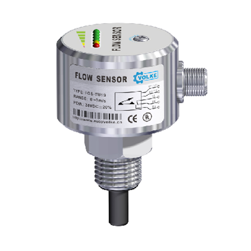


FGS Thermal Conductivity Flow Switch
型号:FGSFGS Flow Switch Working Principle:
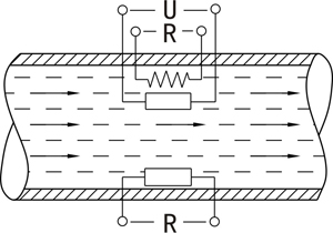
The FGS Thermal Conductivity Flow Switch operates based on the principle of thermal exchange.The probe integrates a heating module and a thermal sensor,where heat transfer is directly correlated with the medium's flow velocity.During measurement,the heating module emits heat.If no medium flows through the pipeline,the thermal sensor detects a fixed heat value.When flow occurs,the heat received by the thermal sensor varies with the medium's velocity.This temperature difference is converted into an electrical signal by the thermal sensor,which is then processed into standardized analog signals or contact signals for flow velocity display and control.
Key Features:
Anti-scaling probe coating to prevent water/rust deposits and enhance contamination resistance;fully waterproof housing design with wide pipe diameter compatibility,adjustable setpoints,and high-pressure resistance up to 60MPa;indicator lights for direct flow status display;effective prevention of debris entanglement.
Technical Parameters:
Measurement Range:Water:0.03–3 m/s;Oil:0.03–3 m/s
Pressure Resistance:4 MPa(Special:60 MPa)
Temperature Response Time:≤12 s
Connection:Thread G1/2",G1/4",others
Switching Time:ON:Typically≥4 s(1–13 s);OFF:Typically≥4 s(1–15 s)
Operating Voltage:DC24V,AC/DC220V
Power Consumption:2W
Output:Relay,NPN/PNP
Contact Rating:0.4A/125VAC,2A/30VDC
Insulation Resistance:50 MΩat 100VDC
Probe Materials:304 Stainless Steel
Housing Materials:304 Stainless Steel
Operating Temperature:–10°C to 60°C
Environmental Conditions:–20°C to 85°C,≤85%RH
Protection Rating:IP67
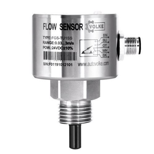
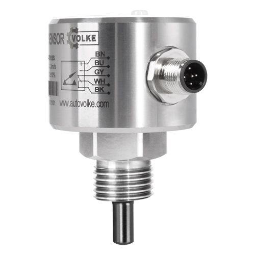
WIRING DIAGRAM:

FGS Thermal Conductivity Flow Switch allows convenient seting of the flow alarm point. Unscrew the protective screwand use the provided screwdriver to adjust the setting knob for configuring the flow alarm point.
For flow switches with PNP, NPN, or relay outputs, the LED indicators signify the following:
- Red light on: Flow velocity below the set point (transistor not conducting / relay not activated).
- Yellow light on: Flow velocity equal to or above the set point (transistor conducting / relay activated).
- Yellow and green lights on: Degree of flow exceeding the set point (green lights 1, 2, 3, or 4 illuminate alongside yellow).

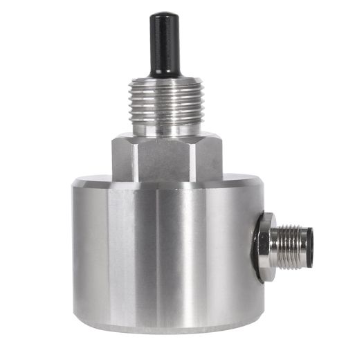
STRUCTURE DIAGRAM:

ORDERING INFORMATION:
